TM 10-4320-307-24
4-6
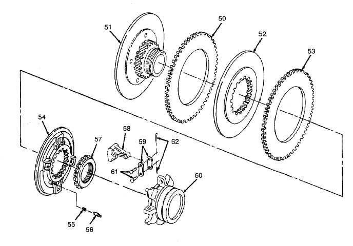
SPEED INCREASER REPAIR (CONT).
2.
Assemble the speed increaser as follows:
a.
Set clutch hub and back plate assembly on bench with hub section facing up.
b.
Install driving plate (50) onto hub and backplate (51).
c.
Install center plate (52) onto first driving plate (50).
d.
Install second driving plate (53) and floating plate (54).
e.
Install adjusting lock pin spring (55) and adjusting lock pin (56) into bore provided in floating plate (54).
f.
Depress pin and spring with a screwdriver while installing adjusting ring (57). Screw ring halfway down hub
thread.
g.
Install four levers (58) and eight lever links (59) to lugs on sliding sleeve (60) with eight lever link pins (61) and
eight cotter pins (62). Spread cotter pins so their ends do not exceed a 0.47-inch (11.94 mm) radius for
operating clearance.
4-32